A macropad is a peripheral you can attach to your computer to allow you to send combinations of keypresses to your computer in one shot. Technically, most of the things a macropad can do are possible by using key combinations on a regular keyboard, I think having a dedicated keyset is pretty helpful for frequently used operations. I will also add encoders to my macropad which are not available in most keyboards and I really miss the tactile nature of knobs for things like volume adjustment.
In this post I am going to capture the process I went throught to build my own macropad. This build is a ‘prep build’ for a Planck-style DIY ortholinear keyboard I want to build in the future, so one of my aims is to practice the techniques I will use for that project.
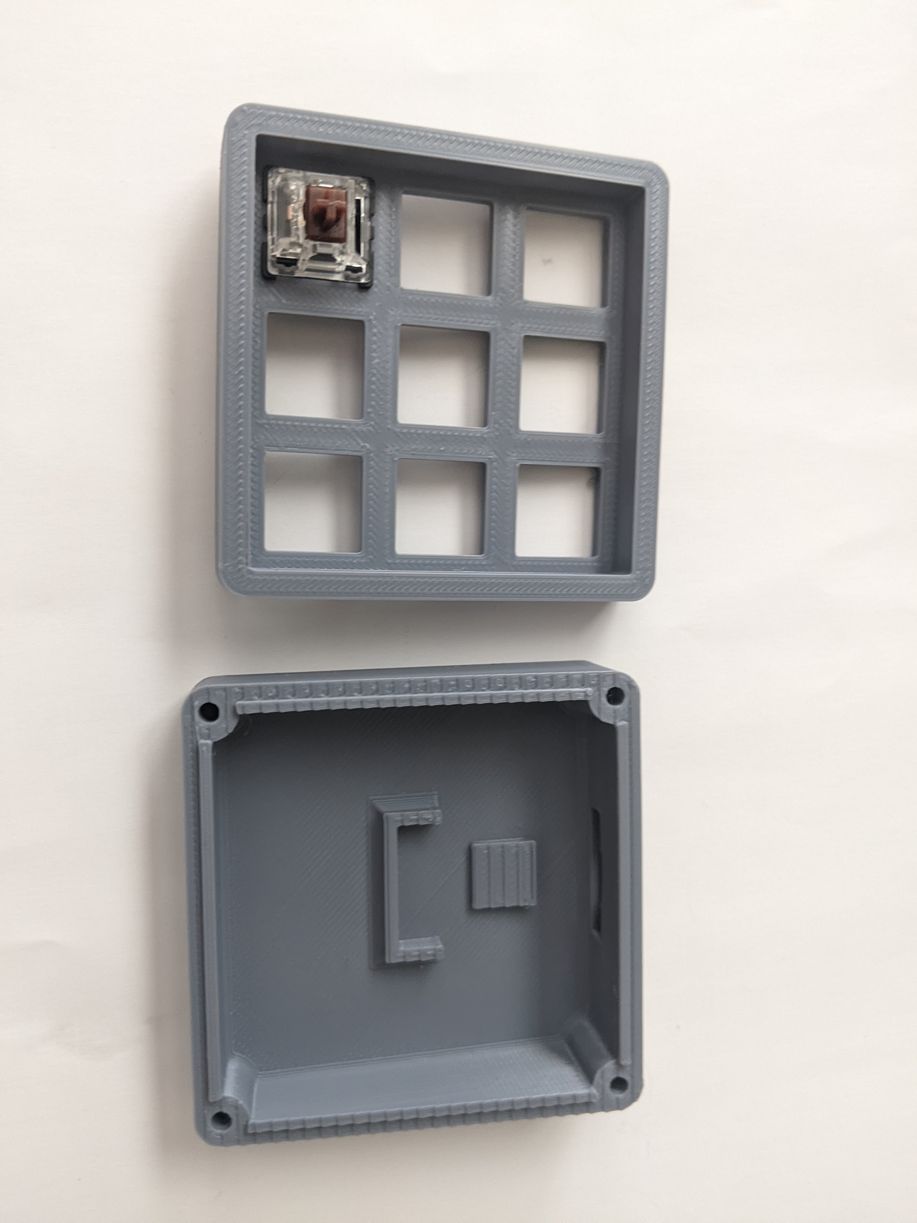
Selecting the case style
I picked the VOID style macro keypad layout (linked below) mainly because the larger keyboard I want to build is a bigger version of this keypad. So I wanted to get a feel for the process of building something in this case and how it looked.
Wiring Vs PCB
There are two main ways of connecting the switches to the driver board: PCB and handwiring. The handwiring route is a bit more complex - since it requires more cable management and good soldering skills. I would imagine that handwired keyboards would also be a bit more fragile. PCBs are significantly cleaner, especially for full-size keyboards, and probably more robust. They would also allow the keyboard to be packed in a thinner form factor.
However, I wanted to keep the cost minimal - and wanted the ability to customize the layout of keys. PCBs tend to be a bit expensive - not necessarily in manufacturing cost, but rather design / turnaround time and so they are not ideal for my use-case right now. Once I have finalized the layout and I want to build something more robust, I might design and order a PCB for the board.
Switches
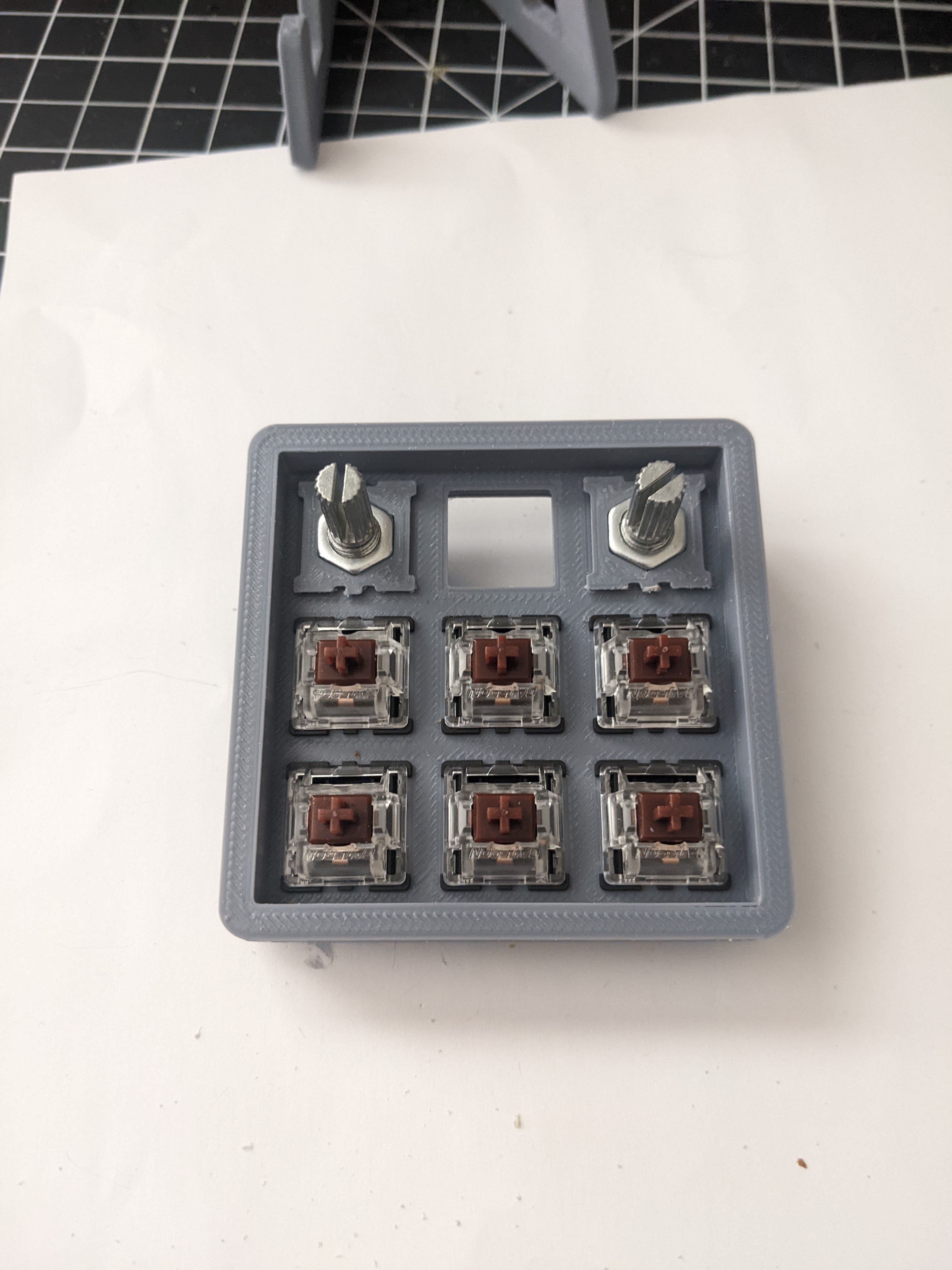
I selected Cherry MX brown style clones from Gateron. They have the right balance of clickiness and noise level for my preference. Since I wanted to handwire this keypad, I decided to get panel-mounted switches as opposed to PCB mounted.
Microcontroller and Firmware
I picked the Arduino Pro Micro microcontroller for the main driver board for the marcropad. I chose it because it seems to provide all the IO pins I need, and provides USB HID functionality required for the device to show up as a keyboard on my computer. It also helps that it’s pretty small in form factor and pretty cheap.
I wanted to avoid writing firmware from scratch and instead use the QMK based firmware for standard configuration. This will allow me to use firmware developed by others and allow me to try out configurators like Vial.
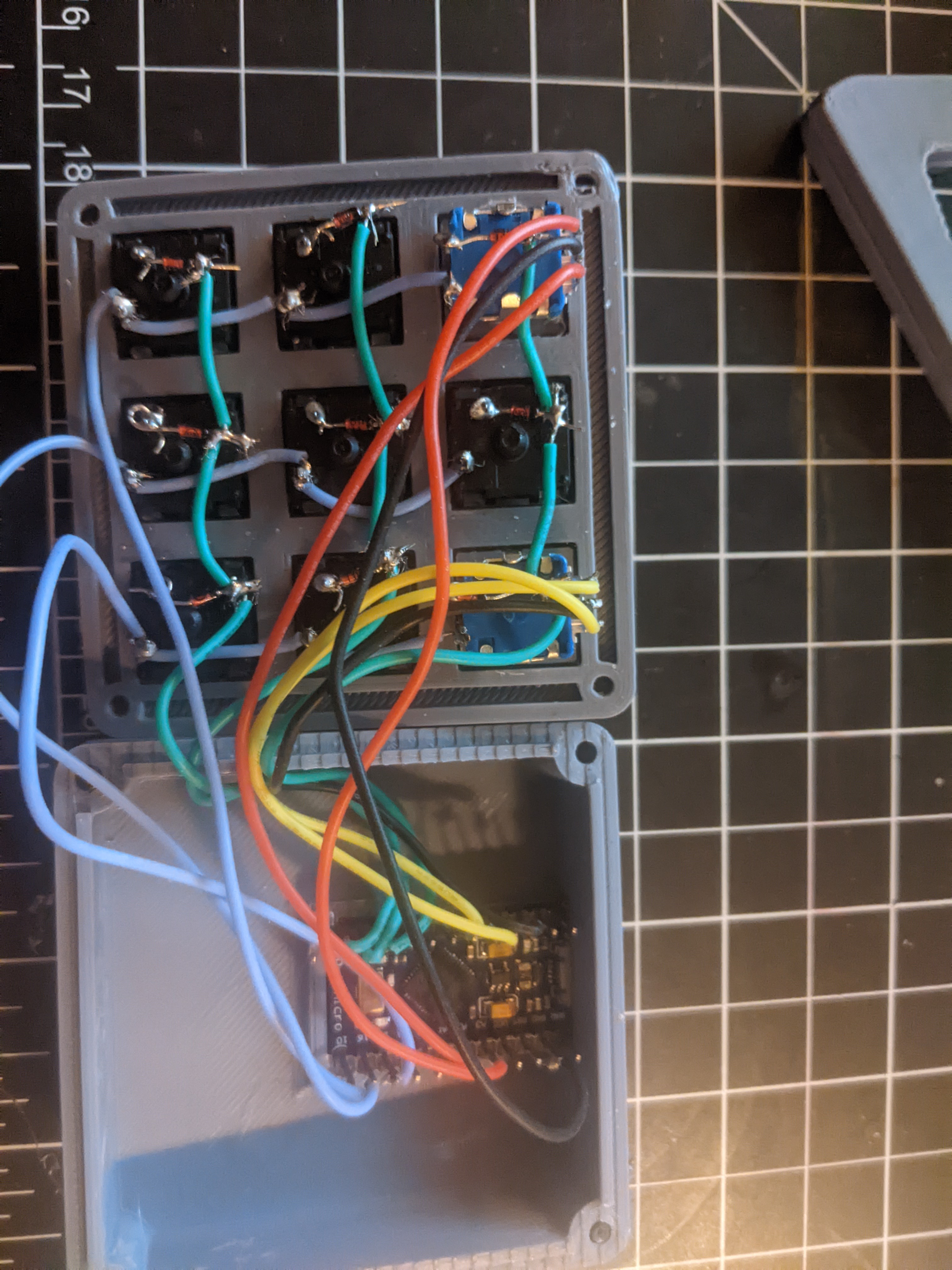
Wiring the Keys
I used deskauthority’s pinout diagram to determine which pins to connect my rows and columns to. I did a bench test before locking the connections and closing the box. Here’s a picture of the configuration showing how I did the test:
Wiring the macropad was q:q
Configuring And Flashing the Firmware
After installing QMK, I created a custom keyboard:
qmk new-keyboard
I gave it the name bhavya/macropad. The default keyboard is 4x4 ortho macropad so I had to change the configuration a bit.
Here’s how my final config’s keymap looks like:
#

enum layers
{
	DEFAULT = 0
};

const uint16_t PROGMEM keymaps[][MATRIX_ROWS][MATRIX_COLS] = {
    [0] = LAYOUT(
        KC_MUTE,   KC_F13,   KC_F,
        KC_F14,   KC_F15,   KC_F16,
        KC_F17,   KC_F18,   KC_F19
    )
};
I decided to map the keys to the fairly generic F13-F19 for the non-encoder keys. I also had to add macropad.c and macropad.h files with some definitions.
The source code for this config can be found in the github link below.
I used http://www.keyboard-layout-editor.com/#/ to build my custom layout, and then used https://kbfirmware.com/ to build the
required keymap to feed into QMK keymap.c and info.json. These two tools don’t give the keymap.c files directly, I used the converter here:
https://qmk.fm/converter/ to generate the info.json from the layout json file. This info.json file is used during the build process
to setup some of the pre-processor definitions required for the code.
A note on flashing the firmware: after quite a lot of trial-and-error and looking at other boards, I found out that I need
to specify bootloader: "caterina" in the info.json. Without this, flashing would not work. This argument is passed to avrdude based on
my understanding of the process.
Encoders
I really wanted encoders in this build - and they arguably the most important feature for me. I picked the EC11 audio encoders from amazon. They were pretty cheap but I had to figure out a way to mount these on my case. Luckily, someone has already made an adapter for this encoder so that they can slot into a standard panel-mounted Cherry MX keyswitch slot.
![Encoder mount] (/macropad_encoder_with_adapter.jpg)
The cool think about the QMK firmware is that it supports encoders out of the box - and not just one encoder - multiple encoders! Setting it up was a breeze - I just had to define a callback function with the required signature to handle the encoder rotation:
bool encoder_update_user(uint8_t index, bool clockwise) {
    if (index == 0) { /* First encoder */
        if (clockwise) {
            tap_code(KC_VOLU);
        } else {
            tap_code(KC_VOLD);
        }
    } else if (index == 1) {
        if (clockwise) {
		tap_code(KC_PGUP);
        } else {
		tap_code(KC_PGDN);
        }
    }
    return false;
}
One of the two encoders on my board, I decided to use one for volume control and use the keypress to mute sink audio. I used the
KC_VOLU, KC_VOLD and KC_MUTE keycodes and they worked pretty much out of the box. The second encoder button press is setup to
‘reset’ the microcontroller - this will be useful for reflashing the pad without having to open it up. The second encoder’s rotation
is setup to do page up / down until I find a better use for it.
Final product
Here’s how the finished macropad looks like:
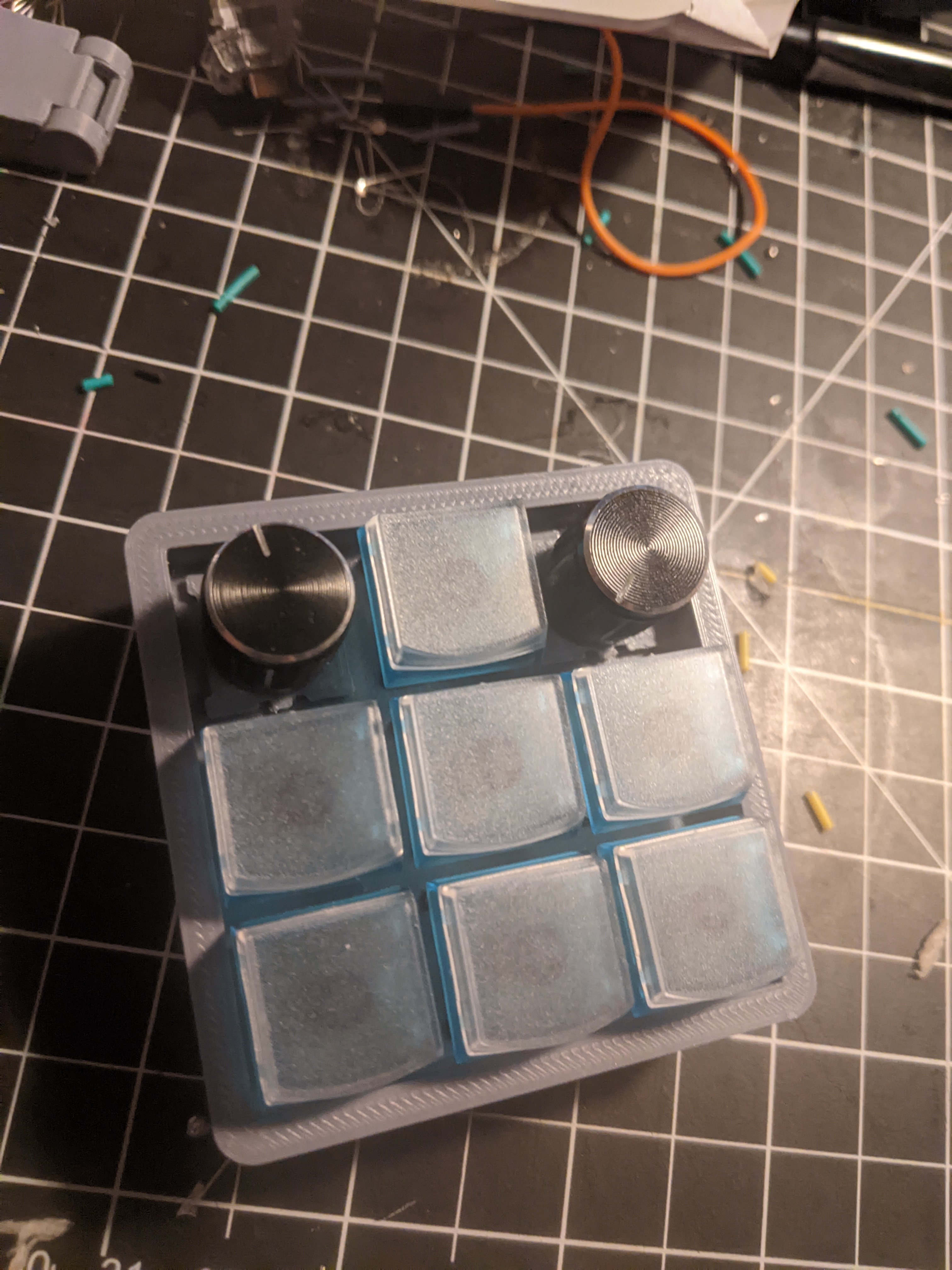
I considered printing out keycap stickers to mark which keys perform what functions. Ultimately, I decided against this for two reasons:
- If I decide to use the multi-layer capability of QMK, fixing the keycap stickers to certain functions will be confusing.
- I want to use this macropad for work and home machines - and arguably the ‘functions’ for these keys will be different in those two contexts.
For some reason, I also couldn’t put in the screws in the case - the diameter was just a tad small, and it seems like the screw holes didn’t have threads, so I probably needed self-tapping screws. Ended up resorting to hot-glue to seal it up (Eww.).
Conclusion
I really enjoyed building this project! I think my soldering and wiring could have been better, and I probably should choose a deeper case to make it easer pack in.